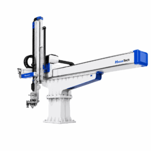
PET preform takeout connects the injection mold with the next handling stage. A robot must remove and transfer the preforms within the available machine sequence, while the cooling process determines when they are ready for subsequent handling. Review both together before selecting a configuration.
A fast transfer movement is only one part of a PET preform production cycle. The preform drawing, mold cavity layout, ejection conditions, end-of-arm tooling and cooling arrangement determine whether the complete hand-off can work as intended. This article explains the project decisions behind that hand-off, rather than prescribing machine settings or a universal cycle time.
Where the Robot Fits
The HT-20C PET preform robot is HecosTech’s existing product for automated preform takeout, transfer and handling. Its published scope includes project-specific tooling and integration with downstream equipment. The cooling arrangement must be defined separately in the project proposal.
Keep equipment roles distinct: the PET preform mold forms the preform; the robot handles its removal and transfer. A cooling station, where required, has its own tooling, utilities and timing requirements. One component description does not establish the specification of the whole cell.
Takeout and Cooling Are Different Stages
In-mold cooling takes place while the preform is still in the injection mold. Takeout is the removal and transfer operation. Post-mold cooling is a separate cooling stage after removal, when the selected production process uses it. Reducing transfer time does not by itself establish that the required cooling has been completed.
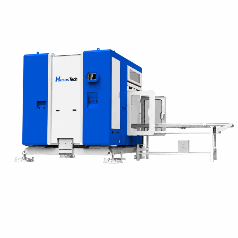
Dedicated preform systems illustrate this distinction. Netstal’s PET-Line describes a side-removal unit with post-mold cooling stations, while SIPA’s XFORM describes post-mold cooling and a preform transfer system. These are examples of those manufacturers’ system architectures, not HecosTech specifications or evidence of cross-brand compatibility.
For a project review, identify where the preforms are held at each stage, when the robot releases them and which equipment owns the next step. If the cooling method or release condition has not yet been defined, record it as an open engineering requirement rather than assuming the robot quotation includes it.
Match the Preform and Cavity Layout
Begin with the preform drawing or sample and the actual mold layout. Preform dimensions, weight, neck design, cavity quantity and cavity positions influence tooling design. A cavity count alone does not describe the distance between pickup positions or the space needed to enter the mold.
Ask the tooling review to cover the supported contact areas, the removal direction, the ejection sequence and the transfer destination. The robot, takeout tooling and receiving equipment must be assessed as a matched set. Do not assume that tooling for one preform will suit another merely because both have the same nominal weight.
For an existing mold, provide its drawings and available removal information before confirming robot travel. For a new mold, discuss the ejection and handling interface while tooling requirements are being defined. This gives the mold and automation suppliers a common reference instead of leaving the transfer arrangement to be resolved after equipment selection.
Check Machine Access and the Hand-Off
Machine tonnage is a starting reference, not a compatibility decision. Mold opening stroke, tie-bar spacing, platen dimensions, mounting position, ejector conditions and available installation space all matter. The robot must have a suitable path into and out of the actual mold, with the complete tooling installed.
Confirm the required machine and robot signals with the responsible equipment suppliers. The injection molding robot system page explains the wider automation workflow; a named interface alone does not verify mechanical fit or every operating sequence.
At the downstream end, define the receiving position, orientation, release method and readiness signal. Where a conveyor system is involved, include its layout and hand-off requirements in the same review. Qualified personnel must validate the integrated sequence using the manufacturers’ procedures and site safeguards; this planning article is not an operating or safety-bypass procedure.
Evaluate the Complete Production Cycle
Separate robot movement time from the molding cycle and any subsequent cooling or handling time. Ask which operations can overlap in the proposed configuration, which must wait for a signal, and where preforms remain while the next molding cycle runs. Do not add or subtract times without understanding that sequence.
If the receiving station is still occupied when the next batch arrives, a shorter robot movement may not resolve the limitation. The review should establish the intended hand-off sequence and the response to a downstream not-ready condition. Do not assume extra cooling stages, storage positions or automatic fault recovery are included unless they are specified.
Agree on the preform, mold, material, tooling, machine and cooling conditions for acceptance testing. Record the complete cycle together with the required part checks, including relevant dimensions, visible handling marks and the condition at release. A result measured with different tooling or an unspecified cooling setup is not a like-for-like comparison, and this article makes no promised cycle-time reduction.
Define the Quotation Scope
A useful enquiry states whether the requirement is robot-only takeout, a robot with application tooling, or a wider cell including cooling and downstream handling. Identify which equipment is already installed and which items should be included in the proposal.
Prepare the preform drawing or sample, dimensions and weight, neck details, mold drawing and cavity layout, machine model and access dimensions, current cycle information, target production requirements and factory layout. Add the available cooling-system details, proposed transfer destination and any required inspection or packing hand-off.
Where information is missing, label it as unconfirmed. Ask the proposal to distinguish included equipment, existing-equipment interfaces, project-specific tooling, utilities and acceptance conditions. This is more useful than comparing nominal robot speed or a headline price without a defined scope. HecosTech’s published PET offering supports a project-specific discussion; it does not establish a universal cooling package or publicly fixed system price.
PET Preform Handling Questions
Does a Takeout Robot Replace Cooling Equipment?
Not automatically. Takeout and transfer describe handling functions. The project must separately define the required cooling method, equipment and release conditions. HecosTech’s HT-20C page states that cooling-system integration can be evaluated; it does not say that every robot includes the same cooling station.
Can an Existing Mold and Machine Be Retained?
They can be submitted for an integration review, but suitability should not be inferred from machine tonnage or cavity count alone. Supply the actual mold, preform, machine and downstream information so that access, tooling, ejection, signal sequence and cooling hand-off can be checked before the configuration is confirmed.
Discuss Your PET Preform Project
Send HecosTech your preform and mold drawings, machine information, cooling requirements and planned downstream process. Review the HT-20C product details or PET preform tooling scope, then use the email or WhatsApp button to request a project-specific quotation.