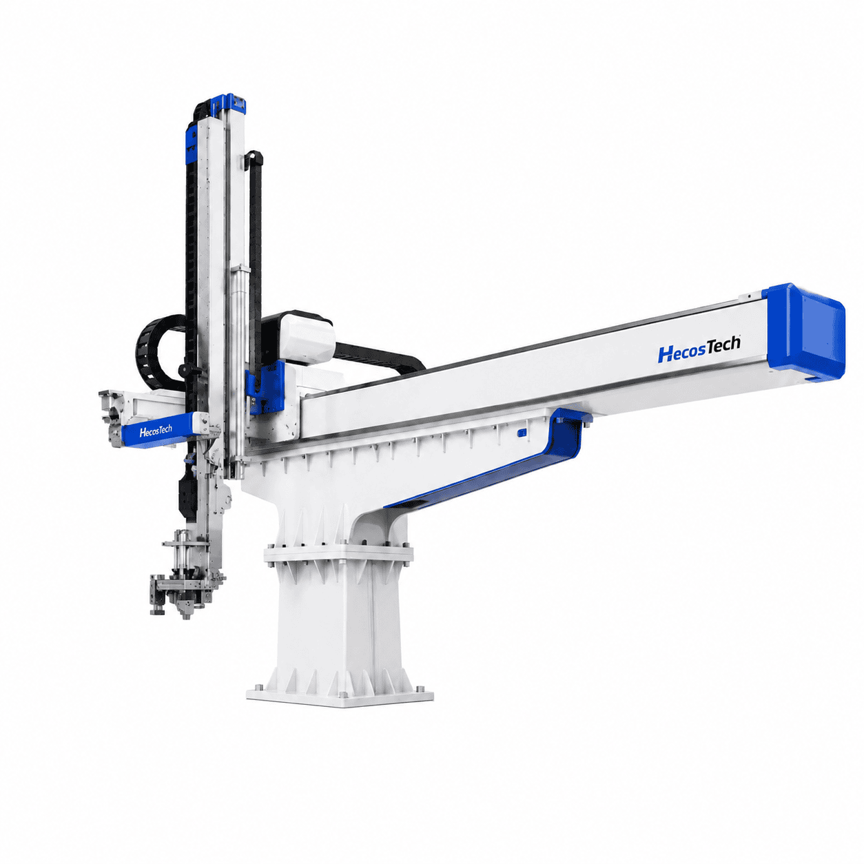
A side entry IML robot moves horizontally into the open mold to place labels and remove finished products. For multi-cavity cups, tubs, lids and other plastic packaging, this layout can shorten the in-mold movement path and coordinate several cavities within the same molding cycle.
However, multi-cavity production should not be evaluated only by the robot’s advertised speed. Label pickup, cavity-to-cavity positioning, product takeout, injection molding machine signals and downstream handling must remain stable throughout continuous production.
Before requesting a quotation, buyers should confirm the product dimensions, cavity quantity and spacing, label format, mold structure, injection molding machine and target cycle. These details determine whether the proposed system can achieve repeatable production under actual operating conditions.
Define One Reference Set for Every Cavity
A multi-cavity project should begin with an identified set of molded components, labels and cavity positions. Record the product drawing or sample used for the review, then identify the cavity count, pitch and orientation shown by the mold reference. This prevents a general product name from being treated as a complete description of the layout.
Use the same cavity numbering across the mold drawing, label set and EOAT discussion. If the cavity arrangement has rows or mirrored positions, show that relationship in the project references. The purpose is not to prescribe a tooling design on this page, but to make sure that every participant is reviewing the same label-to-cavity assignment.
Separate one complete label set from an individual label. A robot cycle may need several physical labels even when the graphics are visually similar. State which labels belong to one mold shot and how each position is identified. A replacement artwork file should not silently change the physical label reference used for handling evaluation.
Record open assumptions beside the affected cavity or component. An unconfirmed orientation, label outline or demolding direction can influence the robot and EOAT discussion even when the container appears similar to a previous format. Marking those items early is more useful than treating the whole multi-cavity layout as confirmed.
For product families, distinguish a graphics-only change from a change in container geometry, cavity spacing or label outline. Each type of change has a different review boundary. A confirmed first format does not by itself establish that every later variant can use the same magazine, EOAT or operating sequence.
How a Side Entry IML Robot Handles Multiple Cavities in One Cycle
In a multi-cavity IML system, the end-of-arm tooling must correspond to the number, spacing and orientation of the mold cavities. It picks up a complete set of labels, enters the mold after a safe open signal, positions each label and coordinates the removal of molded products. A placement problem at one cavity can affect the quality of the entire shot.
Horizontal mold entry can reduce unnecessary travel in suitable packaging applications. However, the actual mold-open time also depends on the robot stroke, tooling weight, mold opening distance, ejector sequence and communication with the injection molding machine. A short empty-cycle demonstration does not guarantee the same performance with actual labels and products.
Stable multi-cavity production requires the label magazine, label retention method, sensors, customized tooling, robot motion, machine interface and downstream discharge to operate as one coordinated cell.
Review the Mold-Open Sequence as a Complete Cell
The useful sequence begins with the machine and mold reaching the agreed handoff condition. Label preparation, robot entry, placement, product takeout, robot exit and the next machine action must be described in order. The sequence review should identify which device provides each signal and which response is expected before the following step.
Existing HecosTech IML robot illustration used to discuss equipment relationships. The image is not a project-specific cycle or clearance approval.
Define the physical handoff at each end of the mold-open window. On entry, the project team needs an agreed mold position, clearance and label set. On exit, it needs a clear condition for the removed components and the robot. These descriptions support the later controls review without publishing an operating program or bypassing machine-specific safety requirements.
Keep the robot motion time separate from the complete molding cycle and from downstream handling. A robot demonstration, an empty movement and a production trial answer different questions. The applicable project documents should state which condition produced each observation so that a partial test is not presented as complete-line evidence.
The broader IML production line workflow explains how molding, label handling, takeout and downstream operations connect. This article remains focused on the side-entry multi-cavity decision and the information needed to evaluate that arrangement.
When the sequence changes, update the affected signal, motion and handoff references together. A downstream change can alter where the robot releases products, while a mold change can alter the available entry path. The project review should identify the changed interface rather than assume the previous sequence remains valid.
Match the Mold, Labels and Injection Molding Machine Before Selection
First, confirm the product dimensions and weight, cavity quantity, cavity pitch, product orientation and demolding method. These factors determine the tooling dimensions, required stroke, handling sequence and space needed inside the open mold.
Next, check the label size, material, shape and placement position. The tooling must pick and place the correct number of labels during every cycle, while electrostatic or vacuum retention must hold each label reliably during high-speed movement.
The injection molding machine brand and model, clamping force, tie-bar spacing, platen dimensions, mold-opening stroke, ejector stroke, signal interface and available installation space must also be reviewed. The target cycle, stacking direction, inspection requirements and conveyor output should be included before the final configuration is approved.
Separate Confirmed Inputs from Design Assumptions
A useful request package separates confirmed data from targets and provisional concepts. Product dimensions, an issued mold drawing and an identified molding machine can be listed as references. A desired cycle, proposed stacking pattern or future variant should be labeled according to its current status rather than presented as an achieved result.
For the molding machine, provide the exact model and the available interface documentation. Also identify the mold and machine arrangement used for the review. Published general dimensions or a machine family name may not describe the installed configuration, accessories or available space around a particular production cell.
For labels, identify the physical reference used in the handling discussion as well as the artwork revision. The graphic file communicates printed content, while the physical label reference supports evaluation of presentation, orientation and pickup. Keep both connected to the corresponding container and cavity arrangement.
For downstream scope, state the required endpoint. Individual components, oriented parts, counted stacks and parts delivered to another machine are different outputs. The quotation should identify which operations are included in the evaluated supply boundary and which equipment or processes remain customer inputs.
The IML automation project checklist provides a structured handover for these inputs. For a broader integrated-cell enquiry, the IML automation systems page remains the commercial destination. This article supports the side-entry decision without becoming a duplicate systems page.
HecosTech HT-20B Side Entry IML Robot for Multi-Cavity Containers
HecosTech HT-20 series robots are side-entry systems. For small and medium multi-cavity container production, the HT-20B side entry IML robot is designed for plastic containers from 0.1L to 5L and can be matched with injection molding machines from 200T to 1000T.
The current HT-20B specification lists a maximum transverse speed of 2.5 m/s and a minimum in-mold time of 1.1 to 2.4 seconds. Actual operating time depends on the product, mold, cavity arrangement, label handling sequence and injection molding conditions.
HecosTech can customize the label feeding system, electrostatic tooling, end-of-arm tooling, product takeout sequence, stacking method and conveyor connection. To prepare a project-specific proposal, provide the product and label drawings, mold drawing, cavity arrangement, injection molding machine brand and model, current cycle, target cycle and required downstream processes.
Evaluate Additional Formats by the Physical Change
A second format should be reviewed according to what changes physically. New graphics on the same confirmed label and component are different from a new label outline, container height, cavity pitch or demolding direction. Describe the change first, then identify the mold, magazine, EOAT, robot path and downstream references that may need another review.
Existing HecosTech packaging illustration showing format variation. Each format remains an example until its product, label, mold and handling references are confirmed.
Create a simple format matrix when several products are being discussed. Give each format its own product reference, label reference, cavity arrangement and required output condition. Mark a tool or sequence as common only after that relationship has been evaluated. Visual similarity alone is not a compatibility decision.
Changeover planning should include the physical items that must be exchanged, adjusted or selected. It should also identify how the correct program and reference set will be confirmed before a trial. This page does not prescribe an operating method; the project documentation and applicable equipment instructions define the actual procedure.
Use the model-specific product page when evaluating a particular equipment configuration. The existing HT-20B link above remains the equipment handoff. The format review here explains the decision inputs and does not replace a project-specific clearance, load, motion or cycle assessment.
Need a Side Entry System Matched to Your Mold?
Send us your product dimensions, label drawing, mold cavities, injection molding machine model and target cycle.
HecosTech can evaluate the complete mold-open sequence and configure the robot, label handling, customized tooling, product takeout and downstream process for your application.
Plan Product Takeout and Downstream Handling Together
A side entry IML robot should not be configured as an isolated label-placement device. Label insertion, product takeout and mold exit must be coordinated within the available mold-open window without delaying the next injection cycle.
Multi-cavity molds discharge several finished products after every shot. The takeout tooling must control product orientation and transfer the products to a suitable stacking, counting or conveying process. If the downstream equipment cannot receive products at the required rate, the complete line may stop even when the robot itself is operating correctly.
Inspection, stacking, conveyor connection and packaging requirements should therefore be confirmed during the initial design stage. This allows the robot path, tooling and line layout to be planned as one automation system instead of adding separate equipment after installation.
Define Transfer, Trial and Acceptance Evidence
For a side entry IML robot, define the transfer endpoint before judging the cell. A molded component released from the mold, an oriented component on a conveyor and a counted stack are different outcomes. The project scope should state which endpoint will be demonstrated and which downstream operations are outside the supplied equipment.
Separate component evidence from sequence evidence. A sample can support review of the molded and decorated component. An observed cycle can support review of the agreed automated sequence. A production trial can provide another type of evidence under its recorded conditions. None should silently substitute for the others.
Record the references used during a trial: product and label revisions, mold and cavity arrangement, molding machine, EOAT and downstream setup. If a provisional part or temporary arrangement is used, state that limitation. A clear record makes later comparisons more reliable without turning one observation into a universal performance claim.
Acceptance responsibilities should follow the defined supply boundary. Identify which party provides the mold, machine, labels, utilities, samples and downstream equipment for the agreed review. The final commercial and technical documents, rather than this general article, define the applicable responsibilities and acceptance conditions.
The IML robot equipment page remains the primary commercial route for the robot range. Send HecosTech the identified product, label, mold, molding-machine and output references for a project-specific evaluation. The proposal can then describe the evaluated configuration without relying on a fixed public price or a universal production promise.
Keep unresolved items visible after the review. A successful label pickup does not settle an open downstream question, and an accepted artwork file does not establish tooling compatibility. Assign each item to its corresponding reference and close it only with the evidence required by the project documents.
Side Entry IML Robot FAQ
Is a Side Entry IML Robot Suitable for Every Multi-Cavity Mold?
No. A side entry IML robot is suitable only when the mold opening, cavity layout, tooling clearance, robot stroke and required cycle allow safe horizontal entry. The product, mold and injection molding machine must be evaluated together before choosing between a side-entry and top-entry robot.
Can One Side Entry IML Robot Run Different Container Molds?
It may support different molds when the robot travel, load, machine clearance and control sequence meet each application. Different products normally require matched end-of-arm tooling, label magazines and operating programs. Changeover time and tooling storage should be included in the project plan.
What Information Is Needed for a Side Entry IML Robot Quotation?
Provide the product drawing or sample, container dimensions and weight, label drawing and material, mold drawing, cavity quantity and spacing, injection molding machine brand and model, current cycle, target cycle, factory layout and required downstream automation. Complete information helps the supplier prepare a realistic technical proposal and quotation.
Build a Stable Multi-Cavity IML Cell
Planning a new multi-cavity packaging line or upgrading an existing injection molding machine?
Send HecosTech your product, label, mold, injection molding machine and production requirements. Our team can prepare a project-specific side entry IML robot configuration, technical proposal and quotation.