
A single-cavity injection mold makes one part per molding cycle. A multi-cavity mold can make several copies of the same part in that cycle. The right choice depends on demand, part design, machine capacity and the complete handling process, not simply on choosing the largest cavity count.
Cavity selection connects a production requirement with a physical tooling layout. More parts per shot may be useful, but the project still needs a suitable mold, machine, takeout method and quality plan. Compare the proposed arrangements on the same basis before treating a lower quoted part price or a higher cavity number as the better solution.
Start With the Actual Part and Production Plan
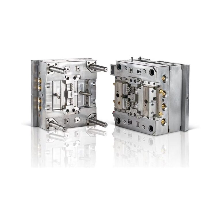
HecosTech’s custom injection mold offering includes project-specific single-cavity and multi-cavity layouts. Its design review considers part geometry, material, tolerances, production requirements and the available injection molding machine.
Provide the part drawing and expected demand even if you have a preferred cavity count. Treat that count as a proposal to evaluate, rather than a confirmed machine specification. An existing mold photograph or a different product’s cavity arrangement does not establish which layout will fit your application.
Distinguish Single-Cavity, Multi-Cavity and Family Molds
For this comparison, a single-cavity mold produces one part per cycle, while a multi-cavity mold produces multiple copies of the same part. A family mold instead combines different components in one mold. Xometry’s overview of injection mold types describes these distinctions and the filling challenges associated with different cavity arrangements.
A family mold is not automatically the right way to make a container and its lid together. Their geometry, material requirements, molding behavior and required quantities need a separate review. This terminology explanation does not establish a HecosTech family-mold specification or imply that different products can share a tool without engineering evaluation.
Keep the comparison tied to the actual parts being ordered. A proposal for several identical parts per shot and a proposal for a mixed set of components do not describe the same output, even if both tools have several cavities.
Compare Required Output With Usable Output
Begin with the quantity needed over a stated period, the planned batch size and the time available for production. Include expected design changes and demand uncertainty. A cavity arrangement intended for a stable recurring order may be different from one for a product whose geometry or order volume is still being evaluated.
For a simple planning comparison, theoretical pieces per hour equal the number of parts produced per cycle multiplied by 3,600, divided by cycle time in seconds. This arithmetic assumes uninterrupted cycling. It does not include rejected parts, setup, downtime or a downstream delay, and it is not a promised HecosTech production rate.
Use the proposed cycle for each configuration rather than assuming both molds will have the same cycle. Then ask what evidence supports the expected usable output under the intended production conditions. Compare the demand for acceptable finished parts with that complete process estimate, not with cavity count in isolation.
Check the Mold and Machine as a Matched Arrangement
Several cavities need a coordinated layout, not just repeated copies of the part drawing. Protolabs’ multi-cavity tooling discussion explains why the flow path, thermal behavior and part arrangement need attention as tooling becomes more complex. Its specific tooling recommendations belong to that supplier’s process and should not be treated as universal limits on HecosTech molds.
Ask the mold designer to review cavity positions, the runner and gate arrangement, cooling, ejection and any movements needed to release the part. Identify surfaces where gate or ejection marks matter to appearance or function. For plastic packaging molds, container geometry and any labeling or stacking requirements also belong in this review.
Check the proposed mold against the actual machine’s injection capacity, clamping requirements, platen dimensions, tie-bar spacing, mold thickness range and opening space. Machine tonnage alone does not verify fit. Keep the final mechanical and process assessment with the responsible mold and equipment teams; this article does not prescribe operating settings.
Compare Tooling Investment and Part Cost Separately
A tooling quotation and a molded-part quotation answer different questions. Ask what is included in mold design, manufacture, trials and any application-specific components, then compare the proposed part-production scope. Keep material, part revision, quality requirements, order quantities and downstream operations consistent across quotations.
More cavities can distribute production effort across more parts per cycle, but that does not establish the total cost of the project. A larger or more complex tool may change the required machine, handling arrangement, maintenance scope or future modification work. Ask suppliers to identify those differences instead of comparing only the headline tooling price.
Consider what happens if demand changes or the part needs a revision. Record the assumptions behind the proposed configuration and the items that would need reevaluation. There is no fixed order-volume threshold, payback period or public mold price that applies to every project. HecosTech uses project-specific quotations based on the actual tooling and production requirements.
Include Takeout, Downstream Handling and Cavity Checks
When parts are removed by a robot, the number and positions of the pickup points affect the end-of-arm tooling and transfer arrangement. Review the whole set of parts, the mold-access path and the receiving position. The injection molding robot system should be matched to the proposed mold and handling sequence, not selected from cavity count alone.
Downstream equipment must be considered at the same time. Confirm how the parts will be placed, separated, stacked, conveyed or inspected, and what happens when the receiving stage is not ready. A higher theoretical molding output is not useful if the next stage cannot accept the intended transfer.
Agree how samples and inspection results will be associated with the relevant cavities during review. Do not assume that one acceptable loose sample demonstrates every cavity’s output or the integrated production sequence. Keep the cavity-layout decision, part acceptance and automation acceptance connected while recording the evidence required for each.
Injection Mold Cavity Selection Questions
Can an Existing Single-Cavity Mold Be Converted to Multi-Cavity?
Do not assume a conversion is possible. The mold base, cavity space, runner system, cooling, ejection and machine interfaces need an engineering review. A different tool may be required. Provide the existing mold information and the proposed production requirement before relying on a conversion in the project plan.
What Should I Send if the Cavity Count Is Not Decided?
Send the part drawing or sample, material requirement, expected demand, batch sizes, relevant quality requirements and available machine information. Add the proposed takeout and downstream handling method. HecosTech can evaluate the tooling requirements from those inputs without treating an unconfirmed cavity count as a final specification.
Discuss Your Injection Mold Configuration
Send HecosTech your part drawing, material, production requirement and machine details. Review the custom injection mold project scope, then use email or WhatsApp to discuss a project-specific cavity layout, tooling scope and quotation.