
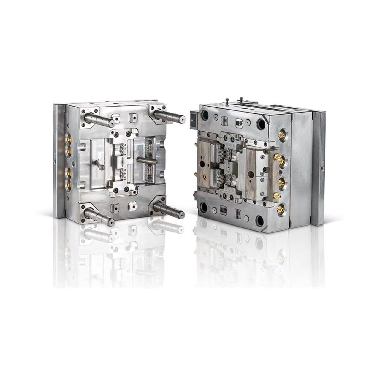
Description
Custom Injection Mold Applications for Plastic Parts
Custom injection mold solutions from HecosTech are developed for customers who need plastic products based on drawings, physical samples or new product concepts. Applications include plastic packaging, household products, logistics products, automotive components, electrical housings, appliance parts and industrial plastic components. Each project is evaluated according to the product geometry, plastic material, appearance requirements, dimensional requirements, expected output and injection molding machine specifications.
Typical projects include plastic containers, caps, buckets, crates, pallets, chairs, housings, panels, fittings and custom technical parts. Depending on the product structure, the mold may require multiple cavities, inserts, sliders, lifters, threaded cores, hot runner systems, special surface textures or automatic demolding mechanisms.
As a custom plastic injection mold project, the product design, mold structure and production process should be developed together to improve manufacturing stability and reduce modification risks.
Custom Injection Mold Design and Manufacturing
Each custom injection mold project begins with a review of the 2D or 3D product drawing, physical sample, plastic material, product weight, dimensional tolerances, surface finish, required cavity number, production target, expected mold life and available injection molding machine.
DFM analysis and mold flow evaluation can be used to identify wall-thickness transitions, undercuts, gate locations, weld lines, air traps, cooling requirements, shrinkage and deformation risks before mold manufacturing. The mold can be configured with a hot runner or cold runner system, single-cavity or multi-cavity layout, two-plate or three-plate structure, sliders, lifters, unscrewing mechanisms, hydraulic core pulling, interchangeable inserts and customized ejection systems.
Draft angle is the taper of a molded surface relative to its release direction. Surface texture, feature depth, resin and the ejection arrangement affect the appropriate taper. Identify fit-critical faces and finish requirements when submitting drawings; a single angle should not be applied to every surface. Protolabs’ draft guidance explains why the actual part needs review.
An undercut obstructs removal along a selected release direction. A parting-line change, revised feature or suitable moving mold component may be considered after reviewing the geometry. Xometry’s side-action overview explains why features formed by a side action need evaluation relative to that action’s movement. Mark the feature’s function and permitted design changes before confirming the tooling method.
The mold interface should be matched with the injection molding machine platen dimensions, tie-bar spacing, injection capacity, clamping force, nozzle interface, mold thickness range and automation space. Dimensional tolerances and acceptance conditions for molded plastic parts may be evaluated with reference to ISO 20457. Final tolerances, inspection methods and acceptance criteria should be confirmed according to the product function and project requirements.
Compare Mold Guiding and Closing Registration
A mold drawing should show how the halves approach each other and which surfaces establish their closed relationship. Keep this internal alignment review separate from fitting the complete mold to the molding-machine platens. Review the proposed contacts on sections through the actual cavity and core arrangement.
| Closing stage | Physical relationship to compare |
|---|---|
| Guide the approaching halves | Identify the proposed guide pillars and bushes, their engagement direction and the plates they guide. Show the relative position while the mold is still open, rather than providing only a closed assembly view. A list of guide components does not describe the complete closing sequence. |
| Establish registration before features overlap | Where additional interlocks are proposed, mark the mating members and when they begin to engage. If cavity and core features cross into the opposite half, show the intended alignment before those features overlap. Do not treat an interlock name as evidence that this sequence has been reviewed. |
| Identify the intended seating surfaces | For a proposed tapered interlock, distinguish contact on the taper from contact between its end faces. DME’s illustrated example seats on the taper without requiring those faces to touch. These component end faces are separate from the mold’s parting surfaces; identify the intended contacts on the project drawing. |
Meusburger describes mold guide pillars and bushes; DME illustrates interlock engagement and tapered seating (pages 3 and 13). These are engineering references, not confirmation of HecosTech components, alignment accuracy, holding capacity or mold performance.
Review the wider injection mold scope or request a custom mold review with the proposed assembly and closing sections.
Trace the Gas Escape Path Before Confirming the Mold
Review each expected last-fill or flow-meeting region on the proposed mold drawing. An air-trap marker identifies a risk; it does not show how gas leaves that location as the cavity fills. Compare the route from the cavity surface to an exit outside the tool.
| Location to review | Physical route to show |
|---|---|
| Region accessible at a parting surface | Where a parting-line vent is proposed, identify its entry at the cavity and follow the groove or slit to its outlet. Show the route on the relevant mold section, rather than marking only the parting line. Identify the surface that must remain accessible for inspection and cleaning. |
| Rib, pocket or region below the parting line | Ask how gas reaches an outlet from within that feature. A proposed local route, such as venting along an ejector pin where suitable, needs its own section and continuation out of the tool. Identify access to the venting component and how it can be cleaned or renewed. |
DME’s venting explanation describes last-fill locations and local paths for ribs or pockets. Its vent FAQ discusses parting-line and pin alternatives. These are engineering examples, not HecosTech component specifications or guaranteed molding results.
Send an annotated section with the proposed gas route, exit and service access. Distinguish predicted air traps from conditions observed during a trial. Keep later condition records in the mold maintenance guide, and request a custom mold venting-scope review.
Two-Plate vs Three-Plate: Review the Mold Opening
Compare the proposed mold section and opening sequence, rather than counting every metal plate in the assembly. The useful distinction is where the cavity and core separate and whether additional plate movement releases the runner.
| Arrangement | Physical layout and selection questions |
|---|---|
| Two-plate proposal | Start at the main split between the cavity and core sides. Identify how this opening exposes the molded part and which side retains it before ejection. Locate the gate and any solid runner relative to that split; show any extra mold movement required by the part geometry. |
| Three-plate top-runner proposal | An additional runner plate arrangement provides movement to release the runner separately. In DME’s illustrated example, the runner is first retained, then released through successive plate separations before the opening for part ejection. For the proposed tool, identify which plate moves at each stage, what it frees, and the order relative to cavity/core opening. |
Review a closed section and the successive open positions. Mark the parting surfaces, components retaining and releasing the runner, any slides or cores that must clear, and the space left for ejectors and pickup tooling. Match total mold height and required opening travel to the intended machine using the actual proposal. Plate count alone does not establish runner technology, cavity count, automatic gate separation or machine compatibility.
Technical reference: DME’s mold-base arrangements and opening example, pages 6, 11 and 94. The example explains a mechanism; the proposed mold drawings determine the arrangement to confirm. For the separate runner-system decision, use the hot runner vs cold runner guide. Discuss your mold opening and machine requirements with HecosTech.
Review Mold Steel Identity, Condition and Inspection
For the proposed mold components, separate the material designation, the delivery or processing condition, and the evidence from an agreed inspection. A grade name alone does not describe all three.
| Review item | What to identify and confirm |
|---|---|
| Material identity | Identify the relevant cavity, core, insert or other component and its proposed material designation. Agree the supporting material document and how its reference or batch identification connects to that component. Keep the material identity distinct from the resin used for molding. |
| Delivery and processing condition | State the proposed supplied condition and any later treatment included for that component. Identify which processing stage a reported hardness describes. A catalogue delivery value does not, by itself, record the condition measured on the finished component. |
| Inspection evidence | Agree which characteristic needs checking, the item or location covered, the method, processing stage and acceptance requirement. Review the actual result and its connection to the component or material record; a document title alone does not define its inspection coverage. |
Keep these decisions in a component-specific material schedule: designation, agreed condition, included treatment and required evidence, with unresolved requirements visible. Review the proposed mold material and evidence scope with HecosTech before confirming the quotation.
Technical examples: Uddeholm’s prehardened steel description and BÖHLER UK’s traceability and additional-testing scope. These describe the manufacturers’ own products and services, not materials or inspection included in a HecosTech offer. Review molded-part samples separately through the mold trial sample approval guide.
Compare Internal Core Cooling Paths
An external cooling connection does not reveal how coolant reaches a deep or narrow core. Compare the internal passages on a section of the actual proposed core, including the features occupying that space.
| Proposed path | What the core section must show |
|---|---|
| Straight drilled route | Show the reachable drilled passage and where it connects. If ejector or sprue-puller features obstruct a through-drilled route, identify that conflict before considering an alternative internal return arrangement. An external connection symbol does not establish the path through the core. |
| Blade-separated baffle | A blade divides outgoing and return flow: coolant travels along one side and returns along the other. Show the blade location and end turnaround. Also examine separation at its sides; clearance that allows coolant to bypass the blade changes the intended route. |
| Central-channel bubbler | In the described arrangement, coolant travels through a central channel, turns outward and returns around its outside. Show the central feed, surrounding return space and outlet on the same core section, rather than recording only a hole diameter or component name. |
DME’s junction overview identifies drilling interference; its baffle FAQ explains side bypass. Autodesk’s engineering definitions distinguish the divided and central-channel paths.
Review the proposed path against the core section before confirming the cooling arrangement. Use the same core revision when comparing proposals, and mark any unconfirmed passage. Keep unresolved flow-path questions with the trial sample approval record and include the section reference in your custom mold enquiry.
Match Mold Cooling Connections to the Production Site
Before confirming the cooling arrangement, connect the proposed mold circuit drawing to the intended production site’s temperature control and water connections. A mold-side layout alone does not establish that the available equipment can serve it.
| Decision | What to show and agree |
|---|---|
| Circuit grouping | Show the proposed cavity, core and insert circuits, their inlet/outlet pairs, and which share a supply or require separate temperature control. Identify proposed series or parallel connections on the drawing; do not select the arrangement from the number of mold ports alone. |
| Mold-to-unit connection path | Show the intended unit or distributor, hose route, internal bore and proposed couplings. Have the technical team review this complete path against the selected equipment’s requirements and available pump performance. Keep changes needed at the mold, connecting lines or equipment explicit. |
| Production-site water interface | Distinguish the unit’s cooling-water inlet and outlet from its mold circulation connections. Confirm the available site arrangement against the selected unit’s documentation, including the specified connection and supply requirements. Record unresolved connections before accepting the proposed layout. |
Technical references: HB-Therm’s system-design explanation and Thermo-6 connection example. These explain review principles, not equipment included in a HecosTech quotation. Keep later condition records in the mold maintenance guide. Review your proposed mold and site connections with HecosTech.
Complete Custom Mold Production Solutions
In addition to the custom injection mold, HecosTech can coordinate injection molding machines, takeout robot systems, in-mold labeling robots, auxiliary equipment, conveyor systems, visual inspection equipment and automation systems.
The final production configuration is selected according to the product dimensions, plastic material, required output, molding cycle, product handling method, quality requirements and factory layout. Mold design, machine selection and robot integration should be evaluated together to reduce equipment compatibility problems and improve production stability.
Customers may purchase an individual mold or request a complete production solution combining the mold, injection molding machine, robot and supporting automation. Contact HecosTech to request a custom injection mold quotation by providing a 2D or 3D drawing, physical sample, plastic material, target output and destination country.
From Mold Quotation to Trial Evidence
Define the evidence needed for the custom mold quotation before treating a trial sample as approval to proceed. The quotation, trial records and release decision should refer to the same agreed product and tooling scope.
Agree the Quoted Verification Scope
Identify the part number, drawing revision, resin grade, appearance reference and functional or mating features. Review these alongside the proposed cavity layout, runner arrangement and intended injection molding machine. Agree the trial material and arrangement, and record differences from the intended production setup. Specify the dimensional, appearance and fit evidence required, who supplies the references and who reviews the results. Confirm the required documentation and its scope with the project contact before the trial.
Trace the Samples and Close the Findings
- Sample identity: connect the samples, photographs and results to the part revision, trial and material used. For multiple cavities, agree how cavity identity, sample coverage, quantity and selection will be recorded for the project.
- Inspection record: identify the feature or surface, its requirement, the measurement or comparison method and the reported result. Keep dimensional, appearance and assembly findings distinct so the evidence answers the agreed question.
- Changes and open items: record the observed condition, relevant requirement, requested action, responsible party and closing evidence. Ask the technical team to evaluate proposed changes and identify affected checks to repeat; preserve the earlier sample record.
State the Stage Being Released
State whether the decision approves the identified samples, requires another trial, accepts a defined deviation or releases a specified production stage. Name the revision, decision owner and remaining conditions. The decision should not silently cover a different tool revision, material or production arrangement.
Use the mold trial sample approval guide to organize the records. Request a custom mold project review to agree quotation inputs, evidence deliverables and approval responsibilities.
Project Review and FAQs
A useful custom injection mold brief should confirm the part drawing or sample, resin grade, appearance surface, functional areas, annual demand, cavity target, compatible injection molding machine, expected part handling method and any assembly or packaging requirements. These inputs help the mold design team review gate position, cooling layout, ejection, inserts, tolerance risk and automation space before steel cutting.
What should I send for a quotation?
For a custom injection mold quotation, provide a 2D or 3D drawing, material requirement, sample photos if available, target production volume, surface finish, dimensional requirements, intended injection molding machine and the destination country for shipment. If automation is planned, include the expected takeout, conveyor, inspection or packing workflow.
Can the mold work with automation?
Yes. When molded parts require stable takeout, labeling, inspection, transfer or downstream handling, the mold interface and production cell should be reviewed together with the robot, conveyor and injection molding machine so that the final layout is practical for factory operation.