
Description
HT-1400Z5 model and project scope
HT-1400Z5 is listed in the HecosTech brochure under injection-molding robots. Use its printed machine reference, travels, equipment dimensions and tooling arrangement to prepare the takeout task and receiving operation. Confirm the supplied configuration against the current project drawing before ordering.
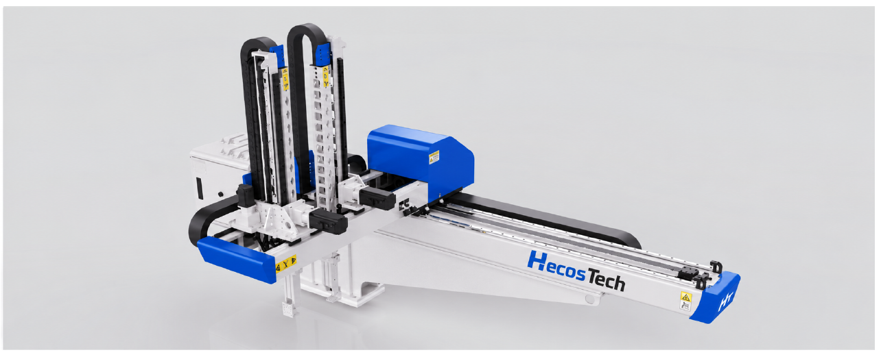
Product illustration: the brochure image is shared by HT-900Z5, HT-1200Z5, HT-1400Z5. It is a family illustration, not evidence of a specific delivered machine or customer project.
Brochure technical specifications
Brochure reference: HecosTech company brochure, printed PAGE/14 (PDF page 9). Values below retain the source field definitions. Pending or unclear fields are omitted; confirm the current drawing and supplied configuration for the order.
| Parameter | Brochure reference |
|---|---|
| Equipment length A | 3,300 mm |
| Equipment width B | 1,800 mm |
| Equipment height C | 1,850 mm |
| Effective transverse travel D | 2,200 mm |
| Effective kick strokes E1 and E2 — each | 300 mm each |
| Effective arm travel | 1,400 mm |
| Standby position: including wrist unit F | 300 mm |
| Maximum transverse speed | 1 m/s |
| Maximum kick speed | 1 m/s |
| Maximum arm speed | 2 m/s |
| Tooling arrangement as printed | Two suction units + two gripping units |
| Arm type | Two-stage arm |
| Injection-molding-machine range, brochure reference | 530–850 T |
| Drive mode and coordinates as printed | Servo motor; coordinates X1/X2/Y1/Y2/Z |
| Maximum load, brochure reference | 20 kg |
| Unloaded takeout time | 3 s |
| Dry cycle time | 8 s |
| Air consumption | 15 NL/cycle |
| Power supply | AC 220 V |
| Power capacity | 4.5 kVA |
| Equipment weight | 700 kg |
| Air pressure | 5–8 bar |
Machine, mold and takeout review
- Machine and mold: Provide the machine make/model and actual machine and mold drawings, mounting references, mold-open/ejector sequence and proposed access path. The brochure machine range is a selection reference, not machine/mold approval.
- Moving load and EOAT: Identify the product and tooling masses separately and ask how the quoted maximum load is defined, including any end-of-arm tooling allowance and load distribution. The printed maximum is not established net product payload.
- Installation and access: Locate the equipment on the project layout. Equipment dimensions and weights do not establish installed clearance, guarding or service access. Confirm drawing datums and any F/G callouts that apply.
- Interfaces and handoff: Define the machine signals, sequence, safety/interlock responsibilities and receiving operation. Identify who supplies and integrates each machine, mold, tooling and downstream item; inclusion and interface approval must be stated in the project scope.
Timing and acceptance conditions
Maximum speeds, minimum or unloaded times and dry-cycle values, where printed, retain their individual definitions in the table. They are brochure references, not the production cycle of a loaded machine/mold/robot cell. Agree the actual configuration, representative samples, operating conditions and acceptance criteria before relying on a target output. This page does not record a completed trial, FAT or customer acceptance.
Compare named models and define the project
Compare HT-900Z5 and HT-1200Z5. Review each named model’s travels, dimensions, load definition and supplied tooling; a shared family or similar value does not establish interchangeability.
Return to injection molding automation selection for the wider task scope. Send the shortlisted model, drawings, product references and unresolved configuration questions for an engineering proposal review.