
Description
HT-T20A model and project scope
HT-T20A is listed in the HecosTech brochure as an in-mold labeling system. Use its printed configuration, travels and component dimensions to prepare a model-specific label-insertion and takeout review. Confirm the supplied configuration against the current project drawing before ordering.
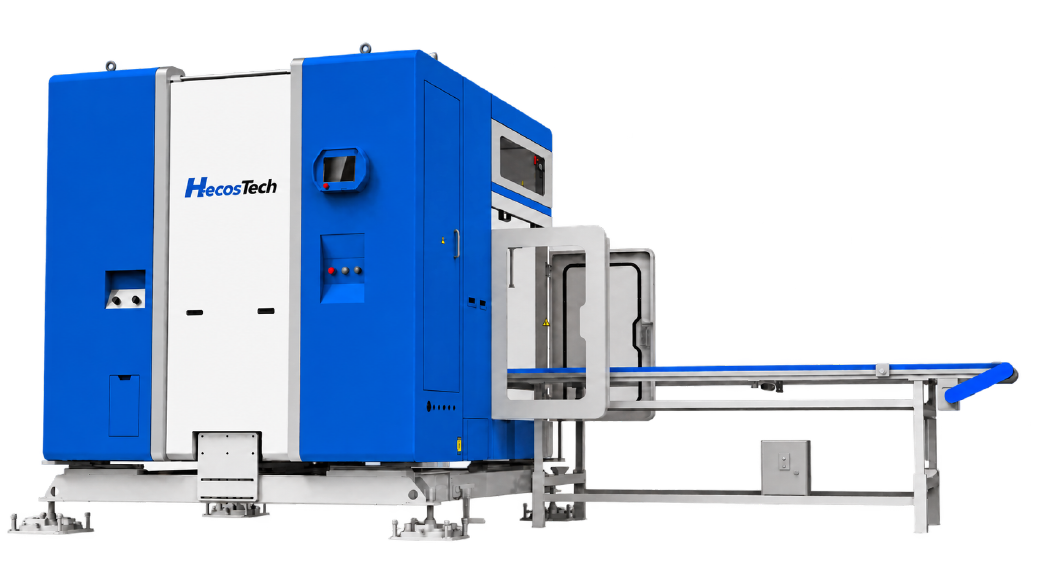
Product illustration: HT-T20A brochure illustration. The image identifies the brochure model, not a delivered customer project or an approved installed layout.
Brochure technical specifications
Brochure reference: HecosTech company brochure, printed PAGE/04 (PDF page 4). Values below retain the source field definitions. Pending or unclear fields are omitted; confirm the current drawing and supplied configuration for the order.
| Parameter | Brochure reference |
|---|---|
| Electrostatic mode | In-mold + outside-mold |
| Electrostatic voltage | 20 kV |
| Equipment length A | 3,100 mm |
| Equipment width B | 2,200 mm |
| Effective transverse travel D | 1,800 mm |
| Effective stacking travel | 400 mm |
| Effective label-pickup travel | 450 mm |
| Label-magazine capacity | 1,000 sheets |
| Maximum transverse speed | 2.5 m/s |
| Fixture rotation | Servo motor |
| Fixture label-pickup method | Vacuum pump |
| Injection-molding-machine range, brochure reference | 200–1,000 T |
| Drive mode and coordinates as printed | Servo motor; coordinates X/Y/Z/A/B/Y1 |
| Maximum load, brochure reference | 50 kg |
| Minimum labeling / takeout time | 2.4 s |
| Dry cycle time | 12 s |
| Air consumption | 50 NL/cycle |
| Fixture application range, brochure reference | 5–33 L |
| Power supply | AC 380 V |
| Power capacity | 12 kVA |
| Equipment weight | 2,500 kg |
The fixture-rotation row specifies a servo motor. Confirm the required rotation range, tooling and supplied control configuration; the table does not define them through the model name.
Machine, mold and labeling review
- Machine and mold: Provide the machine make/model and actual machine and mold drawings, mounting references, mold-open/ejector sequence and proposed access path. The brochure machine range is a selection reference, not machine/mold approval.
- Product, label and magazine: Provide the molded-product and label references, placement position, cavity arrangement and magazine access requirements. Fixture-volume and dedicated/general-purpose descriptions are brochure references, not approval of the complete labeling cell.
- Moving load and EOAT: Identify the product and tooling masses separately and ask how the quoted maximum load is defined, including any end-of-arm tooling allowance and load distribution. The printed maximum is not established net product payload.
- Installation and access: Locate the equipment and label magazine separately on the project layout. Equipment dimensions and weights do not establish installed clearance, guarding or service access. Confirm drawing datums and any F/G callouts that apply.
- Interfaces and handoff: Define the machine signals, sequence, safety/interlock responsibilities and receiving operation. Identify who supplies and integrates each machine, mold, tooling and downstream item; inclusion and interface approval must be stated in the project scope.
Timing and acceptance conditions
Maximum speeds, minimum or unloaded times and dry-cycle values, where printed, retain their individual definitions in the table. They are brochure references, not the production cycle of a loaded machine/mold/robot cell. Agree the actual configuration, representative samples, operating conditions and acceptance criteria before relying on a target output. This page does not record a completed trial, FAT or customer acceptance.
Compare HT-T20A and HT-HD(F)
These two brochure entries share a printed length and power-capacity value, while their width, drive-coordinate labels, equipment weight and air-use entries differ. Review them against the same proposed layout and tooling rather than assuming that one can replace the other.
| Reference field | HT-T20A | HT-HD(F) |
|---|---|---|
| Drive coordinates as printed | Servo; X / Y / Z / A / B / Y1 | Servo; X / Y / Z / A / B |
| Fixture rotation | Servo motor | Servo motor |
| Equipment length A | 3,100 mm | 3,100 mm |
| Equipment width B | 2,200 mm | 2,800 mm |
| Equipment height C | Confirm | Confirm |
| Equipment weight | 2,500 kg | 2,800 kg |
| Power capacity | 12 kVA | 12 kVA |
| Air use | 50 NL/cycle | 70 NL/cycle |
Coordinate labels are not an integer axis count. Both heights require confirmation; equipment dimensions are not installed clearance, equipment weight is not net product payload, kVA is not kW, and NL/cycle is not peak air flow. Confirm the offered configuration and interfaces. Download the seven-model IML comparison reference for an offline review, or return to the full IML model comparison before the project enquiry below.
Compare named models and define the project
Compare HT-HD(F) and HT-16PDA. Review each named model’s travels, dimensions, load definition and supplied tooling; a shared family or similar value does not establish interchangeability.
Return to IML robot selection for the wider task scope. Send the shortlisted model, drawings, product/label references and unresolved configuration questions for an engineering proposal review.