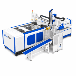
Confirm machine, mold, interface and cycle compatibility before your IML robot is manufactured.
An IML robot for injection molding machine integration must be engineered around the actual machine, mold and production sequence. The injection molding machine brand and clamping force provide useful initial information, but they are not enough to confirm the robot configuration.
The robot must have sufficient access to place labels and remove molded products without interfering with the mold, ejector or machine movements. Its motion must also fit within the available mold-open time and communicate correctly with the injection molding machine.
HecosTech IML robots can be evaluated for integration with different injection molding machine brands and support EUROMAP 12 and EUROMAP 67. Final compatibility must still be confirmed from the actual machine specifications, interface documentation, mold and required automation sequence.
Treat an IML robot for injection molding machine project as a cell-integration task rather than a standalone equipment purchase. The reference package should connect the machine, in-mold labeling mold, label, robot motion, takeout path and downstream handling before the configuration is released.
What Must Match Before IML Robot Integration?
Mechanical matching begins with the actual injection molding machine and mold. Important information includes platen dimensions, tie-bar spacing, mold-opening stroke, mold height, ejector position and sequence, robot mounting position, available floor space and overhead clearance.
The production process must also be reviewed. Product dimensions and weight, label size and position, mold cavity quantity, target cycle time, end-of-arm tooling and required downstream operations all influence robot travel, payload and motion sequence.
Electrical integration requires the correct connector, signal arrangement, safety circuit and operating logic. Before manufacturing begins, the supplier should review the machine model, technical documentation and interface configuration instead of assuming that every machine from the same brand uses an identical setup.
For an IML robot for injection molding machine retrofit, record the installed connector, available signals, safety-circuit responsibility and machine options separately from the nominal interface designation. Current photographs and the electrical drawing help distinguish confirmed inputs from assumptions that still require review.
How EUROMAP 12 and EUROMAP 67 Support Integration
EUROMAP 12 and EUROMAP 67 define electrical interfaces between an injection molding machine and a handling device or robot. They provide standardized signal communication so the injection molding machine and IML robot can coordinate their movements during the production cycle.
These interfaces help manage operating permissions and machine status during mold opening, label placement, product takeout and robot clearance. The correct sequence is essential because the injection molding machine must not begin a conflicting movement while the robot is inside the mold area.
However, EUROMAP 12 or EUROMAP 67 support does not automatically confirm complete project compatibility. Mechanical dimensions, connector configuration, signal assignment, safety requirements, machine options and cycle logic must still be checked against the actual injection molding machine.
EUROMAP 12 or 67: replacement or new equipment?
Identify the actual machine and robot interface before comparing quotations. The official documents reviewed here are EUROMAP 12, version 1.7 (May 2015), and EUROMAP 67, version 1.11 (May 2015).
| Purchasing question | Document scope and selection consequence |
|---|---|
| Replacing equipment on an existing machine | EUROMAP 67, clause 1, limits EUROMAP 12 to replacement on existing equipment. This limitation does not approve a particular replacement robot or machine combination. |
| Specifying new equipment | Do not present EUROMAP 12 and 67 as equivalent default options. Establish the proposed interface and applicable equipment requirements with the machine and robot suppliers. |
| Confirming equipment power requirements | EUROMAP 12 includes a handling-device power-supply chapter. EUROMAP 67 records removal of that clause in its revision history. Confirm actual equipment supply requirements separately from the interface name. |
For a retained EUROMAP 12 machine and a robot proposed with EUROMAP 67, ask both suppliers to document the actual configurations and whether the proposed integration is acceptable. An adapter description alone does not establish this. Qualified engineers need to resolve the equipment-specific assessment before the purchase specification is fixed.
Use the agreed configuration as an input to the responsibility and acceptance reviews below. The cited recommendation editions establish a document comparison, rather than approval of any particular HecosTech model.
Electrical signals, robot data and MES data
If a quotation lists OPC UA, identify the communicating equipment and specification. A data connection alone does not establish the robot interface or the electrical safety arrangement.
| Interface | What the documents address |
|---|---|
| EUROMAP 12 / 67 | Electrical interfaces between the injection molding machine and handling device or robot. Use the equipment-specific electrical documents alongside the purchasing comparison above. |
| EUROMAP 79 / OPC 40079 | Data exchange between the injection molding machine and robot, including production datasets and part tracking. This is a different connection from machine-to-MES data exchange. |
| EUROMAP 77 / OPC 40077 | Data exchange between the injection molding machine and a manufacturing execution system (MES), including information collection and job and dataset management. |
The official EUROMAP 79 page lists Release Candidate 1.00.06, updated March 2024. It states that OPC UA does not exchange safety signals and specifies the EUROMAP 81 electrical interface for those signals. An advertised OPC UA connection is therefore insufficient evidence for accepting the safety interface.
In the interface review below, separate the electrical connection, machine-to-robot data and any MES connection. Ask which functions and document revisions the actual controllers implement. These document roles do not confirm EUROMAP 77 or 79 support for a HecosTech model.
Create a signal and responsibility matrix before the operating sequence is finalized. It should identify who supplies the connector, cable, guarding interface and required machine-side changes, then map mold-open permission, robot entry, label placement, takeout, robot-clear and cycle-restart conditions. The broader IML production line workflow should use the same approved handover sequence.
Acceptance for an IML robot for injection molding machine cell should verify the agreed label-placement, product-removal and clearance sequence with the approved mold and product format. Record which checks are completed at the supplier site and which depend on the production machine at the customer site; an IML automation project checklist keeps those responsibilities visible.
IML Integration Across Global Injection Molding Machine Brands
IML automation can be integrated with injection molding machines from different countries and manufacturers. Representative market examples include China’s YIZUMI PAC380K3 for high-speed packaging production, Austria’s ENGEL e-speed 280 for an IML yogurt-container application, and Germany’s ARBURG ALLROUNDER 720 A for thin-wall IML cup production.
These models are reference examples showing that packaging and IML automation are used across different machine platforms. They do not represent a limited compatibility list, a claim that HecosTech supplied these published demonstration cells, or automatic approval for every machine of the same model.
For a HecosTech project, final matching is based on the customer’s actual injection molding machine, mold, product, label, target cycle and factory layout. This allows the IML robot, tooling, interface and operating sequence to be configured for the real production conditions.

Confirm Your Injection Molding Machine Before Manufacturing
A properly configured IML robot for injection molding machine production starts with verified machine and mold data. Send HecosTech the machine brand, exact model, technical specifications, mold drawing, product information and required cycle before confirming the robot.
This engineering review helps identify mechanical, electrical and process requirements before the system enters manufacturing.
Can You Retrofit an IML Robot to an Existing Injection Molding Machine?
An IML robot for injection molding machine production can often be installed as an IML robot retrofit on an existing machine, provided that the machine, mold, interface, production cycle, and available installation space meet the project requirements.
Before deciding whether to retrofit an IML robot to an existing injection molding machine, the review should confirm mold access, platen and tie-bar dimensions, opening stroke, ejector sequence, robot mounting position, production cycle, and available communication signals. Older machines or machines without a suitable standard interface may require additional electrical work, signal conversion, or customized integration.
Before an IML robot retrofit or IML robot upgrade is approved, the existing mold must also be checked for label placement, product takeout, and robot clearance. The final technical proposal should also confirm the destination country’s voltage, frequency, safety requirements, installation conditions, and the equipment that can remain in the upgraded production cell.
HecosTech IML robots can be evaluated for integration with existing injection molding machines. However, every retrofit must be evaluated from the actual machine and production conditions rather than approved from the brand name alone.
IML Robot Integration FAQ
What Is the Difference Between EUROMAP 12 and EUROMAP 67?
EUROMAP 12 and EUROMAP 67 are separate electrical interface recommendations for communication between an injection molding machine and a handling device or robot. The interface actually installed on the machine must be identified before wiring and programming are confirmed.
Choosing an IML robot for injection molding machine integration therefore requires the supplier to verify the connector, signal configuration, safety circuit and required operating sequence.
Can an IML Robot Work With Any Injection Molding Machine Brand?
HecosTech IML robots can be adapted to different injection molding machine brands. Final compatibility depends on the actual model, mechanical dimensions, mold, interface, cycle time, installation space and production process.
Brand compatibility does not mean that one standard configuration fits every machine. An IML robot for injection molding machine production must be configured from the actual project data.
What Machine Information Is Required for IML Robot Integration?
Provide the injection molding machine brand and exact model, clamping force, platen dimensions, tie-bar spacing, mold-opening stroke, ejector information, interface type, technical manual, current cycle time and factory layout.
The product drawing, label drawing, mold drawing, cavity quantity and required downstream operations are also needed because the robot must be matched to the complete production process.
Planning an existing injection molding machine automation or IML robot retrofit project? Send HecosTech your machine model, mold, product, label, current cycle, interface, and automation requirements. HecosTech can evaluate the existing equipment and confirm the mechanical layout, EUROMAP 12/67 interface, operating sequence, and required upgrade scope before manufacturing.