
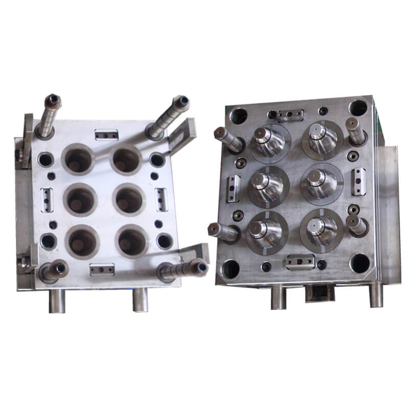
Description
IML Injection Mold Applications for Plastic Packaging
IML injection mold solutions from HecosTech are developed for food packaging, beverage packaging, household products, chemical containers and industrial plastic packaging. Each mold is designed according to the product shape, label structure, plastic material, cavity number and required production output.
Typical applications include yogurt cups, ice cream containers, takeaway boxes, food tubs, plastic lids, paint buckets, detergent containers, cosmetic packaging and other decorated plastic products. These molds can also be developed for thin-wall containers requiring fast molding cycles and accurate label positioning.
This product page covers the custom IML injection mold itself. Within an in mold labeling mold solution, the mold must be coordinated with the label, in mold labeling machine and IML robot. Label size, label shape, cavity layout, product removal and stacking requirements should be evaluated together during mold development.
Custom IML Injection Mold Design
Each tooling project is evaluated according to the product dimensions, wall thickness, label coverage, label material, cavity number, runner system, gate position, cooling design and required molding cycle.
The mold should provide stable label positioning, balanced plastic filling, effective venting, uniform cooling and reliable product release. Depending on the production process, the label may be held against the mold surface by static electricity, vacuum or a customized positioning method.
The mold interface should also match the injection molding machine and IML automation equipment, including platen dimensions, tie-bar spacing, mold opening stroke, ejector requirements, robot entry space and cycle signals. Final specifications are confirmed after reviewing the product drawing, label drawing, machine information and required output.
Geometry and interfaces to confirm at design review
An IML injection mold design review connects the package drawing with the label and handling arrangement. The following questions expand the design factors listed above; they are review topics, not fixed construction details for every mold. Ask for the proposed approach for the actual container before approving a drawing or assuming that an existing tool can be reused.
Decorated surfaces and gate location. Mark the required label coverage on the container drawing, including any bottom decoration, uncovered areas and label edges. Review the proposed gate position against that coverage. The existing IMDA reference explains that gating arrangements can affect decoration and stripping choices. Confirm the intended surface appearance with the proposed tooling arrangement, rather than evaluating the artwork without the part geometry.
Label positioning and mold detail. Identify how the proposed label will be located and held before molding. A description of static or vacuum retention does not replace the relevant mold and label details. Ask which tool features support the chosen approach and whether a change in label outline requires another review. For an existing mold, request an assessment of suitability instead of assuming that the addition of a robot alone makes it an IML mold.
Filling, venting and cooling. Review these items together with the selected plastic material, wall-thickness target and label arrangement. Ask the tooling team to explain the proposed design and the information still required from the package or label supplier. Record unresolved design questions before the review is closed. A general statement about fast molding does not define the filling conditions, cooling requirement or achievable result for a new package.
Release and access. Describe how the finished container is expected to leave the tool and what access the robot needs during mold opening. Include the available machine opening and ejector information in the discussion. Where the package has a lid interface or other functional feature, identify that feature in the review references. Confirm that the tooling and automation discussions use the same product orientation and cavity arrangement.
The useful outcome is an agreed design basis for the IML injection mold, with open questions assigned to the relevant technical team. Keep proposed design decisions separate from results verified on samples. When a container, label or machine reference changes, identify the affected interfaces and agree which part of the review must be repeated before the change is accepted.

Distinguish In-Mold and External Label Charging
A static-retention proposal should show where the label receives charge and how it leaves the robot’s label-carrying core. Compare these two supplier-described arrangements using the intended label and cavity references; the word electrostatic alone does not identify the same tooling interface.
- Charging at the final in-mold position. Simco-Ion’s pinning example carries a label on a dummy core into the cavity. Electrodes in that robot-carried core charge the label at its intended position, after which it transfers to the grounded mold wall and the robot withdraws. Show where the proposed charging elements and label-carrying core sit relative to the actual cavity, rather than recording only the robot stop position.
- Charging before mold entry. In the supplier’s outside-charging example for metallised labels, an external charging bar charges the label before transfer into the mold. Its described dummy core is earthed and semi-conductive. Identify the proposed external charging position and carried-label arrangement; do not assume that relocating the charging step leaves the core construction unchanged.
These are examples from Simco-Ion’s IML process explanation, not universally interchangeable tooling types. The equipment scope, electrical conditions and installation requirements for a HecosTech project are confirmed in its own proposal.
Agree the charging location, core/mold references and transfer responsibility with the tooling and automation teams. Use the static-retention troubleshooting guide for instability symptoms, and include unresolved interfaces in your IML mold enquiry.
Complete IML Mold and Automation Solutions
In addition to the IML injection mold, HecosTech can coordinate in mold labeling robots, in mold labeling plastic labels, label feeding systems, take-out equipment, visual inspection, conveyor systems and automation systems.
The final configuration depends on the product dimensions, label shape, cavity number, molding cycle, product removal method, stacking requirements and factory layout. Mold design and robot design should be coordinated together to improve label positioning accuracy and production stability.
IML Injection Mold Project Information
For a tooling review, useful starting inputs include the product drawing or sample, label artwork and material, plastic material, product dimensions, intended product use, expected production requirement and injection molding machine information available at the site. These details help define the tooling discussion and related label handling, robot, inspection or stacking interfaces.
- Product drawing or sample, dimensions and wall-thickness target
- Label artwork, label material, coverage and positioning requirements
- Plastic material and intended product use
- Expected production requirement and cavity discussion
- Available injection molding machine dimensions and IML automation information
For related IML tooling, review the in-mold labeling mold page. Production automation discussions are also available on the in-mold labeling robot page.
Tooling Configuration and Supply Scope
Compare an IML injection mold proposal against the specific package and production cell it is intended to serve. A mold-only requirement, a mold matched to an existing machine and an integrated production project have different delivery boundaries. Identify the equipment already available and the interfaces still to be reviewed before treating two quotations as equivalent.
For a coordinated cell, the IML automation system discussion covers the relationship between the molding machine, label handling, robot and downstream equipment. The tooling proposal should state which of those interfaces it addresses. A system illustration is useful for locating the mold within the process, but does not establish that every pictured component is included in the mold quotation.

Review the label and container as a matched reference
The label drawing and container drawing should describe the same intended package. Confirm which surfaces are decorated, where the label edges meet and which areas remain undecorated. A graphic preview helps communicate appearance, while the physical label and container references support the tooling and handling discussion. Neither reference should silently replace the other.

If a packaging family contains several sizes, list each container and label combination separately in the project brief. Similar artwork does not mean that two packages share mold geometry, cavity layout or handling tooling. Identify which format is being quoted and which additional formats require a separate technical assessment.

Agree the review outputs before approving the mold
The review should leave a clear record of what is defined and what remains open. Useful outputs for an IML injection mold discussion include:
- Package reference: the agreed container drawing or sample, label reference and material information.
- Machine interface: the available machine information, the proposed mounting and opening requirements, and any details still needing confirmation.
- Handling interface: the label-placement and product-removal arrangement to be coordinated with the robot discussion.
- Supply boundary: the tooling included in the proposal and any separately supplied labels, machine or automation equipment.
- Sample review: the agreed references for checking dimensions, decorated appearance and product release, with acceptance criteria defined for the actual project.
Use the agreed revision of each reference when reviewing a sample or a proposed change. Record whether a comment concerns the container design, printed label, mold or handling equipment. This keeps approval decisions traceable without treating a general product description as a guaranteed cycle time, cavity count or production result.
IML Injection Mold Questions
What information is needed for an IML injection mold quotation?
A product drawing or sample, label artwork, material information, expected production requirement and available machine details provide a practical basis for a tooling discussion.
Can an IML injection mold project include robot and label coordination?
Yes. When the production process uses in-mold labels, the mold discussion can include the interface with IML robots, label feeding, take-out equipment, visual inspection and conveyor systems.
How do I start an IML injection mold project?
Share the available product, label and production information through HecosTech contact so the project scope can be reviewed before a solution is proposed.
Customers may request an individual mold or a complete production solution combining the mold, injection molding machine, robot, label and supporting automation. Contact HecosTech to request an IML injection mold quotation based on your product drawing, label artwork, sample and production requirements.
A clear project brief can also indicate whether the requirement is stand-alone tooling, a mold matched to an existing injection molding machine, or a wider IML packaging production discussion. This keeps the review centered on verified product geometry, label interfaces and related production steps.